Robots

8051 Microcontroller Software
![]()
Mobile Robot (MicroMouse)
Click for a bigger image 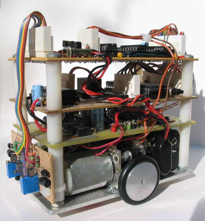
A new single board to replace all the small Cybot boards has been designed is now at the prototype stage. It will be a 'plug-in replacement' taking Cybot from a toy to a serious research tool. An SMBus (I2C) connector to match that on the original Cybot processor boards is included. This should allow RR expansion boards to be plugged in if desired. These are the main features beyond those already on Cybot.
Click
for a bigger image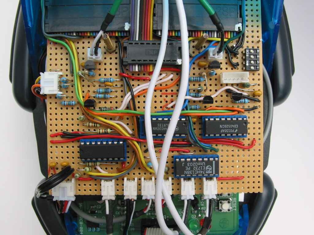
* 2 x extra Sonar channels
* 4 x short-range Infra-Red distance measuring channels. Can also be used for passive IR detection of the ball in Junior RoboCup football.
* 2 x wheel tachometer (odometry) interfaces.
* 2 x general purpose digital input/output lines.
* 2 x interrupt lines (e.g. for 'bumper' switches).
* 1 x analogue output. This could be used, for example, to drive an audio amplifier and loudspeaker providing sounds other than just 'beeps'.
* Enhanced light detection (able to take level measurements).
* Enhanced line following capability. Can now also be used for position sensing on a Junior RoboCup greyscale marked football pitch.
* Motor speed variable in 256 steps.
* Rechargeable batteries can be used.
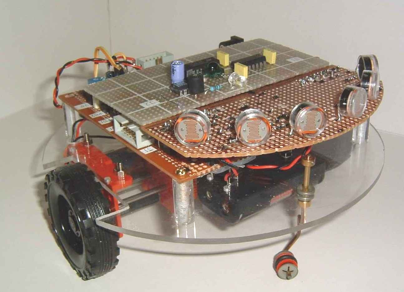
A light following function has been implemented so far to test out main functions such as motor control. The green board is the Cygnal development board containing only the processor. The length of stripboard mounted above it contains all the other chips and connectors for motors, sensors, etc. Sonar is now working using new transducers which provide much sharper beamwidth. The ribbon cable hanging out of the back in the picture is the JTAG link to the MCU chip from the PC-based development system. Programs are downloaded and debugged via this cable. Cybot's IR communications board has been interfaced and provides for remote control using a LEGO Mindstorms remote unit.
Click for a bigger image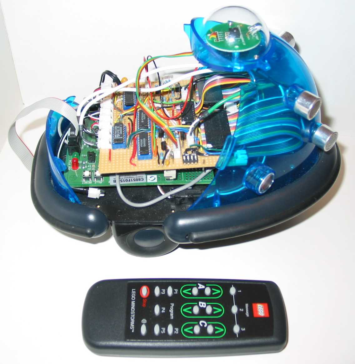
If Cybot senses no light above a programmed threshold, it does a 360o sweep on the spot until it finds a source. Once found it will head towards the source. The sensor outputs are subtracted to provide a proportional error signal: the sign indicates left or right turn and the magnitude determines how much the appropriate motor is slowed down to bring about the turn. Hence a light source dead ahead yields zero error and both motors go full speed forward. A light nearly sideways on will produce a large error and the motor on that side will almost stop, causing Cybot to slew round fast. Smaller errors produce smaller steering effects. If the light disappears, Cybot returns to sweep mode. Cybot uses its wheel tachometer to determine when it has turned a full circle.
Sonar
The sonar system is now working. The receiver circuit has been changed to give it extra sensitivity (See revised schematic Vsn 1.7 above). I had a big problem with the RR transducers: the beamwidth is so wide the transmitted pulse was being picked up by the receiver directly. I now use the HY12 type as sold by Maplin. They're bigger, but fit nicely on the outside of the front shield. The beamwidth is much narrower now, giving greater resolution. For instance a broomstick can be resolved at 1m range. The transmitter is just 'kicked' with a single 50 microsecond pulse. The transducer is a highly tuned device so it just responds by resonating at its natural frequency of 40 kHz for a few cycles.
Click for
a bigger image 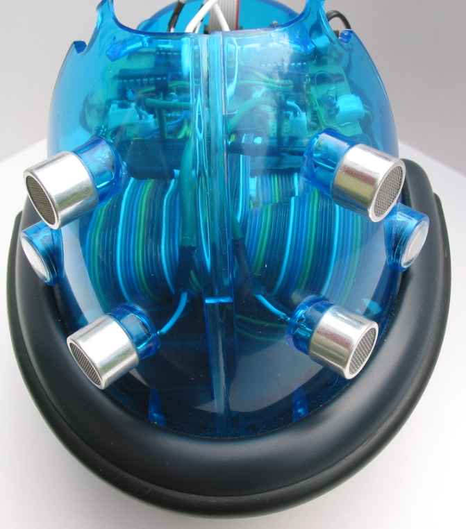
The Cybot IR comms board plugs into a 5-way socket, and remote control using a LEGO handheld unit has been established. I used the LEGO unit because the RCX comms protocol is well documented and it didn't take long to figure out the significance of each of the 11 bytes transmitted when a button is pressed! Baud rate is 2400 with 8 data bits, odd parity bit and 1 stop bit. Like Cybot the motors can be driven forward and back by pressing buttons. Unlike Cybot however, these manual controls will overide any automatic program running. So if the robot gets stuck it can be driven out of trouble. Releasing the motor button returns Cy-Q to the original program.
A Versatile Modular Mobile Robot
NovaBot is my latest project based on my experience with Cy-Q. This robot is very modular, sensor-rich and up to five can be chained together to give you anything from a 4WD articulated planet explorer to a caterpillar. It is based on a disc of perspex 17.6cm in diameter to keep it within the regulation size for RoboCup Junior football, and uses a pair of widely available plastic gearbox and motor sets, but with an 8-hole tachometer wheel added to each motor shaft. It is completely symmetrical front-to-back with a castor at each end. These castors are detached when two or more are linked together. The main processor board follows the same symmetry with sensor/expansion 'stations' at each end and in the middle. The photo of the prototype (right) shows the IR comms board in the centre station and an LDR sensor board at the front.
Click for a bigger image